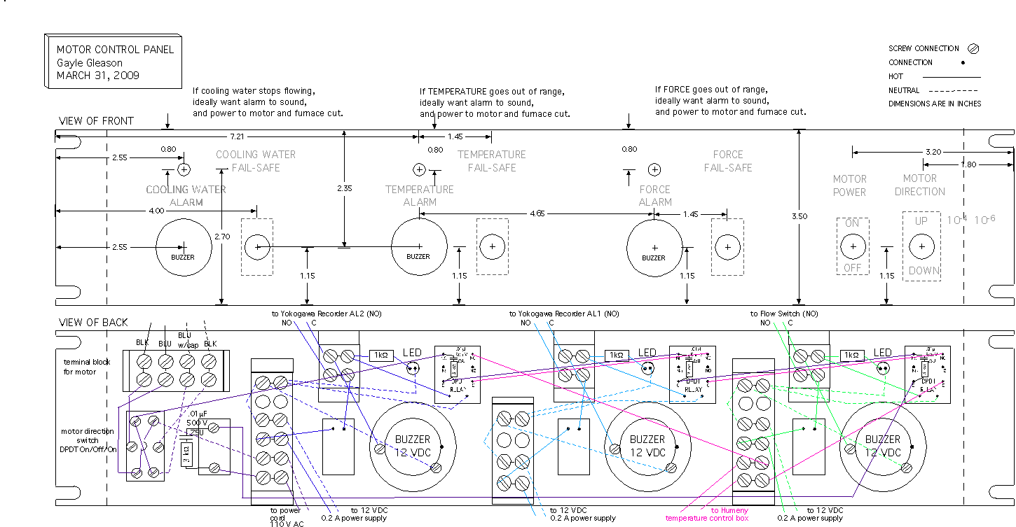
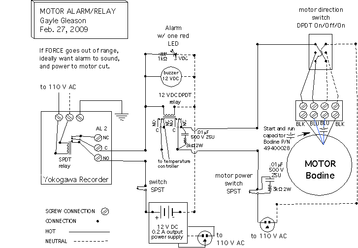
The following schematics are a design that I came up with (with help from Curtis Gleason and John Driscoll) to control the motor that drives the force piston and to cut power to the motor and furnace should the force or temperature go out of range and trigger the alarm on my Yokogawa DX1006 Daqstation data recorder. The motor control portion has been tested and works, but the alarms have not been fully tested. I am posting this on my webpage for those of you who may be refurbishing your own Grigg's rig and are looking to see how some one else did it. Please keep in mind that I am NOT a licensed electrician! I only pretend to be one in my lab.

The following circuit diagram is for just one of the alarms above, however the other two alarms are identical except that they loop through the AL 1 or the cooling water flow switch instead of AL 2. Note that the circuit supplying power to the motor goes through all three alarm relays. The Bodine motor is P/N 07410005 B (4 wire reversible).
